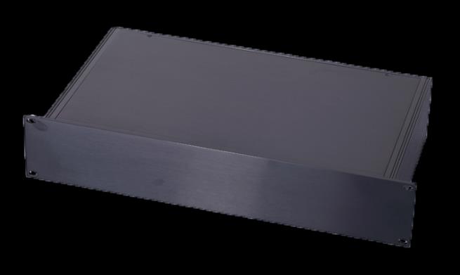
The EMTS 100W 40dB attenuator box reduces high power RF signals by a fixed 40 dB in one compact enclosure. It is typically used at DAS and POI headends, where base station output levels must be brought down to the input range of the distribution equipment.
The unit provides four input ports and four output ports with 4.3-10 female connectors, so several signals can be conditioned in one box. Check the technical specifications below and the datasheet for the power rating, frequency range and environmental limits.
| Technical Specifications | |
|---|---|
| Type | Built-in 4 Attenuators |
| Attenuation | 40dB |
| Accuracy | ±2dB |
| Frequency Range | 3300 to 4100MHz |
| VSWR | ≤1.25 |
| PIM3 | ≤-155dBc |
| Impedance | 50 Ω |
| Rated Power | 100W |
| Connector Type | 4.3-10 Female to 4.3-10 Female(4 PCS Input Ports and 4 PCS Output |
| Operating Temperature | -20°C ~ +50°C |
| Relative Humidity | 5%~95% |
| Dimensions | 19-inch 2U chassis(485mm x 350mm x 90mm) |
| Weight | ≤ 12Kg |
| Application | Indoor |
A high power attenuator reduces the level of an RF signal by a fixed amount while safely dissipating the excess power. In DAS and POI headends, base station outputs are often much stronger than the input level a DAS or master unit accepts, so an attenuator brings the signal into the correct range before it is combined and distributed.
This group contains a 100 W, 40 dB attenuator box. According to its specification, the unit has four input ports and four output ports with 4.3-10 female connectors and an operating temperature range of -20 °C to +50 °C. As a result, one box can condition several base station signals in a compact enclosure.
Fixed attenuators are passive components, so they need no power supply or configuration. However, they convert the absorbed energy into heat, which is why the power rating and the cooling space matter for continuous operation.
Always confirm the power rating against the strongest signal in the system, including future carriers. In addition, consider the whole headend design together with the point of interface module and RF hybrid matrix. Return to all 5G coverage solutions.
This is sometimes possible, but operators often keep base station settings fixed. An attenuator adapts the level at the interface without changing the base station configuration.
Compare the base station output level with the maximum input level of the POI or master unit. Then select an attenuation that brings the signal into range with some margin.
Contact EMTS to confirm the right attenuation for your headend.