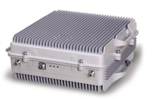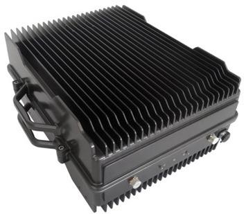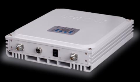
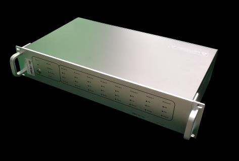
Fiber Optic DAS Master Unit (MU)
The EMTS Telecom Services Ltd. Fiber Optic DAS system is built out of two main components: MU (Optical Master Unit) and the FRU (Fiber Remote Unit). EMTS provides high-end solutions for any system components to ensure your fiber DAS system's high performance. The optical master unit (MU) converts the BTS RF signals from RF to an optical signal using optical cables transmit. It provides a fiber interface to RU, converts RF to fiber (DL), converts fiber to RF (UL), and balances fiber losses. The optical Fiber Remote unit (FRU) reconverts the optical input signal to RF and feeds it to the antennas. It's designed for modularity and high performance. It is the end unit in the system and connects directly to the antenna system. The FRU includes amplification modules in multiple output levels and various combinations of various frequency bands, filtering modules, optical to RF, and RF to optical converters. It provides USB or WIFI connectivity for local settings and a wireless modem for remote control and alarm. The EMTS Fiber optic repeating system is a cost-effective and practical solution for extending signal coverage in subways, tunnels, etc. for indoor or outdoor distribution systems.
Key Features
- Designed to support TETRA/DMR/PMR/LMR Mission Critical Services at 800MHz bands
- Fully comply with TETRA and APCO25 standards
- Fiber optic DAS (Distributed Antenna System) extends network coverage in shadow zones
- Expand signal coverage or fill the signal blind area where weak or unavailable signals such as tunnels, railway stations, enterprises, hotels, airports, etc
- Customized design for TETRA/PMR/LMR, Suitable for large-scale indoor installations
- One Master Unit supports up to 4 or 8 remote units
- Low optical transmission loss, stable and improved signal transmission quality
- A USB port provides a link to a notebook for local supervision
- Advance feature of WIFI connectivity for local setup
- Remote monitoring and alarm through the master unit
Technical Specifications
| Technical Specifications | |
|---|---|
| Items (Uplink) | Downlink |
| Frequency (MHz ) (805-825 MHz) | 850-870 MHz |
| Bandwidth | Fix band – Specific band will be specify |
| Transmission Distance | ≤ 20Km |
| Max. Input Level (Non-destructive) | +10dBm |
| Output Power (RF) | -10±2dBm (Uplink) |
| Output Power (Optical) | 0±3dBm (1310nm) / -6±3dBm (1550nm) |
| System Gain (Cable Access) | 0±3dB |
| VSWR | ≤ 1.5 |
| I/O Impedance | 50Ω |
| Connector (RF Connector) | 1x N Female |
| Optical Connector | 4 RU: 4 x FC/APC 8 RU :8x FC/APC |
| Optical Receiver Sensitivity | ≤ -15dBm |
| Temperature Range | Operation: – 20°C to+ 50°C |
| Relative Humidity Range | ≤ 95% (non-condensing) |
| Power Supply | AC 220V,50/60Hz or-48 V DC |
| Dimensions | 19-inch rack 3U hight |
| Weight | ≤12kg |
| Application | Indoor (IP40) |
| Monitoring and Control | USB (for Local settings) 4G Modem (for Remote Monitoring using EMTS NMS ) |
| Comply with Standards | |
| Safety | EN60950-1, EN 50385 |
| EMC | EN 301 489-1, EN 301 489 |
| DMR | ETSI Technical Report TR 102 398. |
| Technical Specification TS 102 362 parts 1 to 3. | |
| CE | Comply areas, office buildings, subways, tunnels, and shadowed areas. The EMTS coverage solution supports all major |
| mobile technologies and standards of wireless Networks. | |