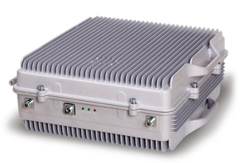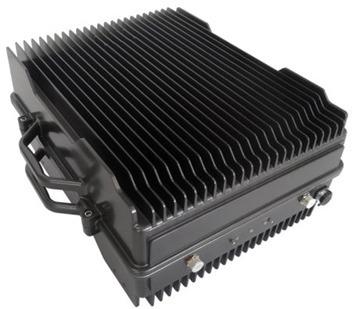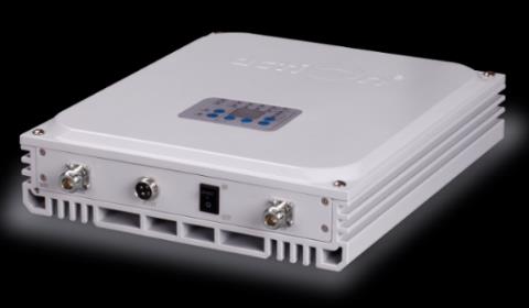
ILB-150-33W40 VHF High Performances In-Line Booster
The EMTS LMR/PMR In-Line Booster (ILB) offers a robust solution to mitigate insertion losses from passive components and transmission losses in feeder cables, particularly in indoor distribution systems and tunnel coverage scenarios. By deploying the ILB, LMR/PMR operators can effectively expand the service area of a base station, offsetting feeder losses through signal amplification along coaxial or leaky cables utilizing Advanced Bi-Directional Technology.
The ILB's lightweight design, straightforward installation process, and user-friendly GUI enhance ease of deployment and operation. This solution is a cost-effective and practical option for improving signal coverage in areas with limited LMR/PMR network reach, such as buildings, shopping centers, airports, and tunnels. The ILB seamlessly integrates into passive Distributed Antenna Systems (DAS) via coaxial cable connections, offering a wide range of configuration options to meet diverse customer requirements.
Key Features
- Optimized for Indoor and Tunnel Coverage: Designed for indoor distribution systems and tunnels
- Advanced Bi-Directional Technology: Employs bi-directional amplification to ensure signal integrity
- Multiple Power Options: Available in 30 / 33 / 37 dBm composite power types, compliant with LMR//DMR system standards
- APCO-25 and Analog VHF Compatibility: Supports all configurations of APCO-25 and analog VHF band operations
- Rapid RF Coverage Expansion: Enables quick deployment of RF coverage within an LMR network
- Compact and Robust Design: High-performance, waterproof enclosure suitable for indoor/ outdoor
- Metal Cavity Filter Technology: Delivers improved receiver-transmitter separation, gain flatness, enhanced stability, and a lower noise figure
- Flexible Connectivity: Equipped with Wi-Fi or RJ45 port options for local monitoring, remote management through the built-in wireless modem, interfacing with the NMS
Technical Specifications
| Technical Specifications | |
|---|---|
| Downlink | Uplink |
| Electrical Specifications | |
| Frequency Range (136-174 MHz) | 136-174 MHz |
| Bandwidth | For uplink and downlink 1 to 5MHz with a gap of 3MHz or more |
| Output Power (33dBm) | 20dBm |
| Gain (40±3dB) | 40±3dB |
| In-band ripple | ≤3dB |
| Gain adjustable range | ≥30dB |
| Gain adjustable step | 1dB |
| Noise figure | ≤4dB |
| VSWR | ≤2:1 |
| Transmission delay | ≤5us |
| Spurious | ≤-36dBm (9KHz to 1GHz) ≤-30dBm (1GHz to 12.5GHz) |
| External connection | |
| Connector | N-F / 50 ohm |
| Alarm Detection | HPA, LNA, TEMP, PSU, Digital IF module, Door Local LED display, Dry Contacts; RS232 local monitoring |
| Local Alarm; | Via RJ45 connectivity using web browser PSU, HPA, LNA, Digital IF Module, Temp, Door open |
| NMS interface | Using ethernet connectivity or 3/4G modem |
| Power Supply | 110 to 220VAC ±15% 50-60Hz / 100 Watts Optional 24 Vdc or -48 Vdc |
| Environmental | |
| Operating Temperature Range | -20 to +55 °C |
| Cooling | Convection |
| Environmental Sealing | IP65 |
| Operating Humidity | Up to 95% (non-condensing) |
| Complies with | EN 301 489-18, ETSI TS 101 789-1, EN 60 950 |
| Standards | 450×400×295 mm |
| Weight | 18Kg areas, office buildings, subways, tunnels, and shadowed areas. The EMTS coverage solution supports all major mobile technologies and standards of wireless Networks. |