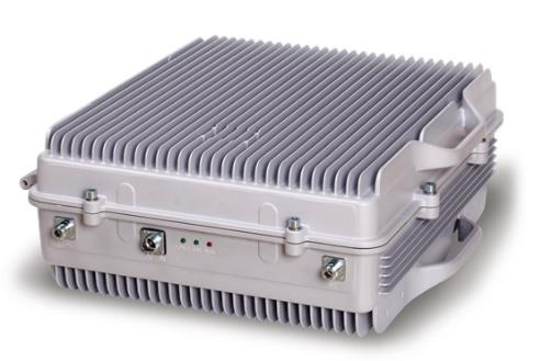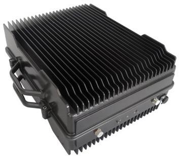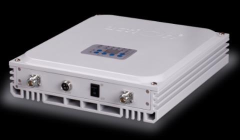
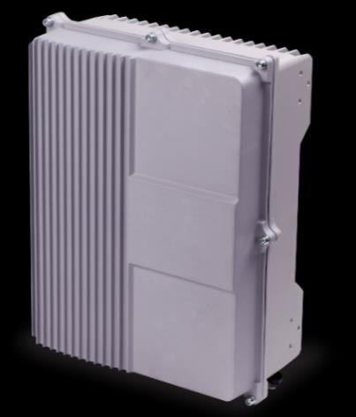
Digital Channel Selective Bi-Directional Amplifier
The EMTS Telecom Services Channel selective VHF BDA provides an excellent solution to extend VHF network coverage for Indoor or Outdoor uses; for Indoor it can feed a lucky feeder or Distributed Antenna System; using the BDA, the LMR operator can easily expand a base station’s service area by filling in coverage holes caused by terrain, buildings, or tunnels. The BDA amplifies the signals from LMR BTS using a downlink amplifier, and the signals from the handset are transmitted to the BTS using an uplink amplifier. The BTS signals are selected via the digital engine, and the signals transmitted from the BDA to the BTS are filtered via a digital engine. The donor antenna transmits signals from the VHF handset and receives signals from the BTS. Easy installation, lightweight design, and very friendly GUI make our BDA easy to use and install. The EMTS BDA is a cost-effective and practical solution for extending signal coverage and includes a wireless modem to support remote and monitoring NMS.
Key Features
- Off-the-air VHF channel selective Bi-Directional Amplifier
- Utilizes advanced digital IF technology, Channels controlled locally or via NMS
- Intelligent design, with built-in ALC function, provides auto amplitude compensation
- It is designed to support Mission Critical Services for the VHF system at the 136-174 MHz band
- The VHF channels for indoor DAS to expand signal coverage and fill the signal blind area where VHF signals are weak or unavailable, using Channel-selective capabilities
- Stable and improved signal transmission quality
- The off The-Air BDA uses to extend network coverage for indoor or outdoor uses
- Aluminum casing with IP66 protection highly resists dust, water, and corrosion
- WIFI or USB port provides a link to a notebook for local supervision or to the built-in wireless modem to communicate with the NMS (Network Management System)
Technical Specifications
| Technical Specifications | |
|---|---|
| Electrical Specifications (Uplink) | Downlink |
| Frequency Ranges (MHz) (136-174 MHz) | 136-174 MHz |
| Operational Bandwidth | 1-5MHz band for uplink and 1-5MHz band for Downlink The frequency separation between uplink and Downlink is 2 to 10 MHz |
| Digital channels | Up to 8 X 25KHz Channel settings can be set via GUI |
| Gain | 90 dB ±2 dB |
| Gain Adjustment Range | 30 dB in 1 dB step |
| Pass Band Ripple | ≤±1.5 dB |
| Output Power (30dBm) | 37 dBm |
| AGC Range | 20 dB |
| VSWR | 2:1 |
| Noise Figure @ Max Gain | 5 dB |
| Spurious | ≤-36dBm (9KHz to 1GHz) ≤-30dBm (1GHz to 12.5GHz) |
| Group Delay | 35 μs |
| External connection | |
| Connector | N-F / 50 ohm |
| Alarm Detection | HPA, LNA, TEMP, PSU, Digital IF module, Door |
| Local Alarm; | Via RJ45 connectivity |
| Local | using |
| LED display, | Dryweb browser |
| Contacts; | PSU,local |
| RS232 | HPA,monitoring LNA, Digital IF Module, Temp, Door open |
| NMS interface | Using ethernet connectivity or a 4G modem |
| Power Supply | 110 to 220VAC ±15% 50-60Hz / 120 Watts Optional 24 Vdc or -48 Vdc |
| Environmental | |
| Operating Temperature Range | -20 to +55 °C |
| Cooling | Convection |
| Environmental Sealing | IP65 |
| Operating Humidity | Up to 95% (non-condensing) |
| Complies with | EN 301 489-18, ETSI TS 101 789-1, EN 60 950 |
| Standards | 428*328*175mm |
| Weight | 18Kg |
| Standard | Comply with CE requiemnts |