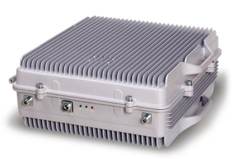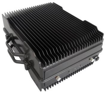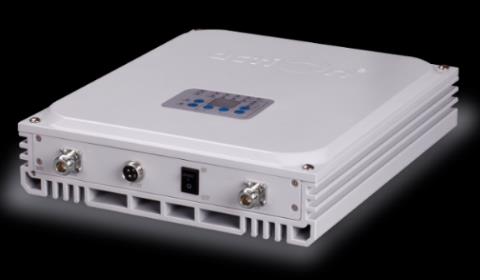
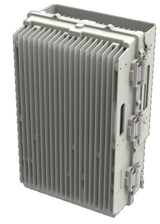
33dBm VHF Band Selective Bi-Directional Amplifier (BDA)
The EMTS Telecom Services Ltd. VHF band selective Bi-Directional Amplifier (BDA) provides an excellent solution for
in-building applications to the problem of poor signal coverage or outdoor coverage extension. Typical applications
are airports, tourism regions, tunnels, factories, mining districts, villages, hotels, exhibition centers, basements,
shopping malls, offices, parking lots and others. With the EMTS BDA, the DMR operator can quickly expand a base
station's service area by filling in coverage holes caused by terrain, buildings, or tunnels. The BDA amplifies the
DMR/LMR/PMR handset signals and base stations and can be used in dead areas where service is poor. Using a coaxial
cable, the BDA is connected to an outdoor 'donor' antenna. The donor antenna transmits signals from the
DMR/LMR/PMR handset and receives signals from the BTS. Easy installation, lightweight design and very friendly GUI
make the EMTS BDA easy to use and install.
Key Features
- Bi-Directional Amplifier configuration for off-air signal operation, Comply with DMR/LMR/PMR standards; Fully transparent to the P25/TETRA /Analog networks
- Designed to support voice data and dispatch; Provide quick RF coverage extension to the radio network
- Linear power amplification effectively suppresses inter-modulation and spurious emission with extremely low power consumption
- Metal cavity filter technology allows wider receiving/transmitting separation, higher stability and lower noise figure
- Intelligent design with a built-in ALC function provides auto amplitude compensation
- Water proof enclosure suitable for outdoor and indoor deployments
- USB port for local supervision; built-in 4G modem to communicate for remote management and configuration. WiFi connectivity for local settings via mobile app
- Web GUI NMS using cloud base with diagnostic function that sends error messages via email in case of faults
Technical Specifications
| Technical Specifications | |
|---|---|
| Electrical Specifications (Uplink) | Downlink |
| Frequency Range1 (147-174MHz) | 147-174MHz |
| Uplink-Downlink guard band | 5MHZ |
| Pass Bandwidth | 5MHZ |
| Gain | 85dB (±3dB) |
| Gain Adjustment Range | 30dB in 1dB step |
| Pass Band Ripple | ±1.5dB |
| Composite Output Power (24dBm (±1dB)) | 33dBm (±1dB) |
| AGC Range | 30dB |
| VSWR | 1.5:1 |
| Noise Figure @Max Gain | ≤5dB |
| Superius Emission & Intermodulation | Fullyc omply with ETSI TS151 026 |
| GroupDelay | 5μsec |
| External connection | |
| Connector | N-F/50ohms |
| Alarm Detection | HPA, LNA, TEMP, PSU, Digital IF module, Door Local LED display, Dry Contacts; via4G modem |
| Local Setting | Through RJ45/USB or WIFI connectivity |
| Remote management and alarms (optional) | Via 4G modem using EMTS cloud base NMS |
| Power Supply | AC220V (+/-15%) with charging capability of -48VDC battery for power backup (the battery supplied by customer) |
| Power Consumption | <80 watts |
| Size (WxHxD) | 447mm X 357mm X 171mm |
| Installation | Wall or Pole mount |
| Environmental | |
| Operating Temperature Range | -30 to+55 °C |
| Cooling | Convection |
| Environmental Sealing | IP65 |
| Operating Humidity | Up to 95% (non-condensing) comply with ETSI EN300019-2-4 |
| MTBF | >100,000 Hours |
| Comply Standards | EN 301 489-18, ETSI TS 101 789-1, EN 60950 |
| Certification | CE comply 1 The Uplink and Downlink frequencies shall be defined by the customer. |
| andwireless networks' standards. | Specificationmaychangewithoutnotice |