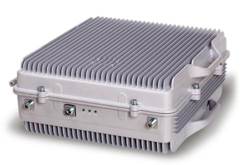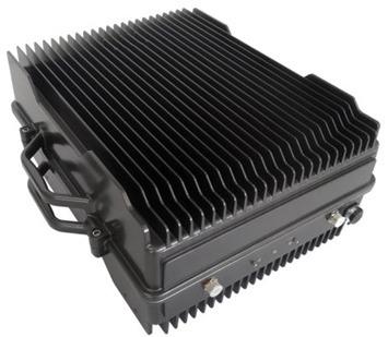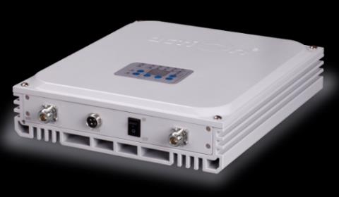
5GNR TDD Band N78 Fiber DAS Master Unit
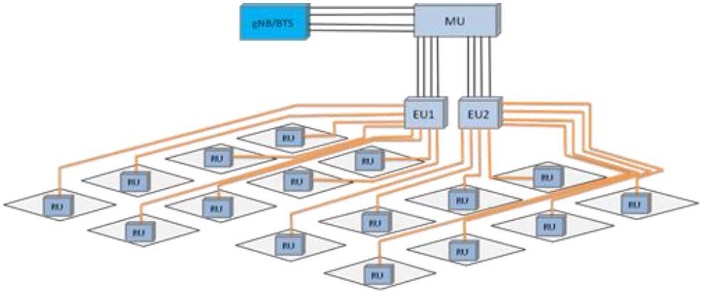
The EMTS Telecom Services Ltd. F/O DAS solution provides an affordable solution for multi-operator 5G indoor signal coverage problems for multi-operator deployment. The Master Unit (MU) is based on POI, Attenuator box, and Fiber Conversion Box Unit (FCB). One Master Unit (MU) is connected to 2 Extension Units (EU). Each EU is connected to 8 Fiber Remote Units (FRU) via fiber optic cables. The gNB RF signals of all 4 operators are fed to the 5G POI. The POI combines all 4 operators into 4 MIMO streams. The combined RF signal is attenuated using an attenuator box and fed into the FCB. The MU converts the RF signal to an optical signal, 1 signal per MIMO stream. The optical signal is connected to the Extension Unit (EU) through F/O cables. One MU supports 2 EU. The EU splits the optical signal from the MU into 8 optical signals for the fiber Remote Unit (RU) via fiber optic cable. The fiber RU will reconvert the optical signal into an RF signal and provide the signal to the areas where network coverage is inadequate. The mobile signal is also amplified and retransmitted to the BTS via the opposite direction. The EMTS 5G Fiber Optic Repeater system is designed to support MIMO 4X4 topology. The EMTS Telecom Services 5G DAS solutions boost network performance to stay ahead of the fast-moving 5G multi-operator deployments & get a fast ROI simultaneously.
Key Features
- Master Unit is based on the standard 5G EMTS POI connected to an Attenuator box and Fiber Conversion Box (FCB)
- 5G RF Extension 4 x4 MIMO system supports TDD technology
- Allows fast 5G NR network deployment
- Designed to comply with ETSI 3GPP TS 38.106
- Supports NSA (Non-Standalone) and SA (Standalone) 5G network
- One Master Unit can support 2 Extension Units (EU), and One EU can support Up to 8 Fiber Remote Units (FRU) to maximize the utilization of fiber optical cable (a star topology is formed between EU and FRUs)
- The POI combines the 4 mobile carriers into 2 X 4 outputs
- The 4 outputs from the POI will be equalized using the attenuator box
- Can be managed through OMT/NMS
Technical Specifications
| Electrical Specification | |
|---|---|
| Item | Specification |
| Supported Bandwidth | 270MHz |
| Frequency Range | 3300 to 3570MHz |
| Signal Mode (Analog/Digital) | Analog |
| The Max. RU Quantity Single MU(4X4) Can Support | 16 |
| Support 4X4 MIMO | YES |
| RF Connector Type / Number (BTS side) | 16×4.3-10 Female |
| Fiber Type (EU side) | Single Mode |
| Optical Wavelength | UL: 1310nm/DL: 1550nm |
| Optical Connector Type/ Number | 8xSC/APC (4X4 MIMO) areas, office buildings, subways, tunnels, and shadowed areas. The EMTS Telecom Services coverage solution Sub-Unit – Point Of Interface (POI) specification |
| Item | Specification |
| Frequency Range | 3300 – 3570 MHz |
| Number of Inputs (BTS side) | 16 Inputs |
| Number of Outputs (Attenuator box side) | 8 Outputs, Only 4 are used |
| VSWR / Return Loss RF | ≤ 1.288 / ≥ 18 dB |
| Insertion Loss (dB) | ≤ 4.5 dB |
| Isolation (dB) | ≥ 28 dB |
| Power Handling (W) | ≥ 400 watts |
| PIM | ≤ -153dBc @2x43dBm |
| Applications | Indoor DAS |
| Connector type | 4.3-10 Mini Din |
| Weight (kg) | 35Kg |
| Size | 19-inch box Hight 6U |
| Operating Temperature (°C) | -20 up to 55°C Deep 46cm |
| Relative Humidity (%) | 95% Sub-unit – Attenuator Box – specification |
| Item | Specification |
| Attenuation | 40dB |
| Accuracy | ±2dB |
| Frequency Range | 3400~3800MHz |
| VSWR | ≤1.25 |
| PIM3 | ≤-155dBc |
| Impedance | 50 Ω |
| Rated Power | 100W |
| Connector Type /Number | 8 x 4.3-10 Female: 4 x Input Ports and 4 x Output ports |
| Operating Temperature | -20°C ~ +50°C |
| Relative Humidity | 5%~95% |
| Dimensions | 19-inch 2U chassis (485mm x 350mm x 90mm) |
| Weight | ≤ 12Kg |
| Application | Indoor 100W 40dB Attenuator 100W 40dB Attenuator 100W 40dB Attenuator 100W 40dB Attenuator Attenuator Box areas, office buildings, subways, tunnels, and shadowed areas. The EMTS Telecom Services coverage solution Sub-Unit – Fiber Conversion Box (FCB) specification |
| Item | Specification |
| RF Connector Type / Number (Attenuator box side) | 4×4.3-10 Female |
| Fiber Type (EU side) | Single Mode |
| Optical Wavelength | UL: 1310nm/DL: 1550nm |
| Optical Connector Type/Number | 8xSC/APC (4X4 MIMO) |
| VSWR | ≦1.5 |
| Maximum Gain @DL/UL | -5±2dB |
| Manual Adjustable Attenuator | ≥15dB/Step 1dB(*per band) |
| Noise Figure@4RU connection | ≦5dB |
| Maximum Input Power (Non-Destructive) | +10dBm |
| Optical Receiver Sensitivity | -12dBm |
| Optical Output Power | ≥-4dBm |
| Max RF Output Power (UL) | -10±2dBm |
| ALC Range | ≥20dB |
| Protection | IP30 |
| Local Monitoring Interface | RJ45 and Wi-Fi Hotspot |
| Remote Monitoring Interface | Cloud NMS via 4G Wireless Modem and RJ45 Interface |
| Room Operating Temperature | -10 ~ +45°C |
| Operating Humidity | ≦95% |
| Dimension (H x W x D) (mm) | 485mm×350mm×88mm |
| Mounting Type | Rack Mounting |
| Weight (Kg) | ≦10kg |
| Power Supply | AC100-240V, 50/60Hz |
| Power Consumption | 60 watts |
| Protection Design: Short Circuit, Over Voltage, Surge | Supported |
| Protection, or High-Temperature Protection Design | |
| Battery Backup / Time | External Battery for 30min (to send alarm message etc.) |
| MTBF | >50000hr |
| Automatic level adjustment to compensate for the | Supported |
| optical loss | |